Free Shipping over $49
- From Ma Junior, an outdoor lighting and outdoor sports enthusiast
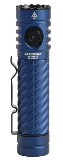
 | I have just bought an EC20 from ACEBEAM. It integrates RGB and white light in a compact size. It features a magnetic tail for easy attachment and is powered by a 3300mAh 18650 USB-C rechargeable battery. In this article, we gonna dive deeper by disassembling it and having a closer view of its inner layout. |
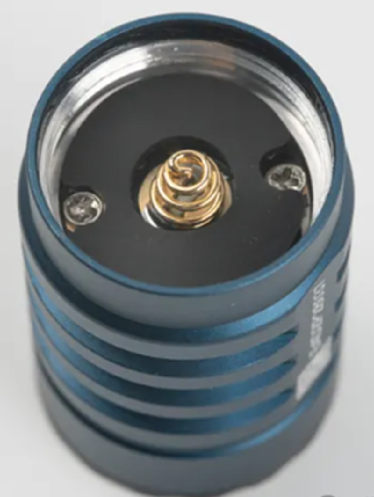
 | First, Remove the tail cap and take out the battery |
 | Step 2, remove the rubber insulation layer |
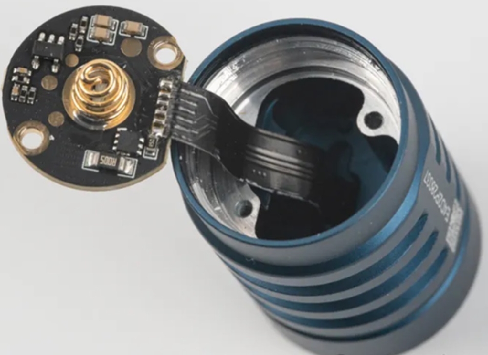
 | Step 3, remove the circuit board |
| Finally, remove the FPC ribbon cable
|
| Now, let us remove the stainless steel strike bezel to have a look at the design of the light board. |
| The board features three SFT-25R HI white main light LEDs for illumination, along with three RGB LEDs. Notice the black part on the light board — that’s the FPC ribbon cable connecting the main control board to the light board. As expected, the light board uses a copper substrate with a thermally isolated design. The "thermally isolated copper substrate" has an astonishing thermal conductivity of 380W/mK — that's 380 times better than aluminum substrates! This technology is perfect for high-power lighting, and it seems there’s really no alternative that can match it. Now, let's talk about the FPC ribbon cable. From the end, it appears to be a double-sided trace design. The thicker traces on both sides are used to power the white light main LEDs. The four thinner traces in the middle, on both the front and back, are for driving the three RGB LEDs. Since the copper-based light board is a single-sided board, the connection between the FPC ribbon cable and the copper substrate is done as follows: six soldering holes are made at the FPC end and soldered to the copper substrate's pads. The other end of the FPC is threaded through a slot in the center of the copper substrate, passes through the integrated heatsink structure of the lamp head, and is finally soldered to the pads on the main control board. |
In all the flashlights I've previously disassembled, the connection between the light board and the main control board was made using silicone wires. If this flashlight had used silicone wires as well, it would have required two thicker silicone wires and four thinner ones, for a total of six. This would make the soldering and assembly process quite difficult. However, the FPC ribbon cable used in this flashlight solves this problem very effectively. It’s designed with enough slack for the soldering process, and when everything is reassembled, the FPC ribbon cable only needs to bend in one direction at a few points, so it won't get crushed. Moreover, by adding reinforcement plates in sections, the bending points of the FPC ribbon cable can be controlled.
Overall, the ACEBEAM EC20 is an EDC flashlight that combines aesthetics, practicality, and fun.
It's so interesting to see the inner workings of a flashlight. thanks :)
Nice teardown! Looks like there's some great electrical engineering that's gone into this one.